- hacker
?chadez
DCS810 Digital Servo Drive experiments
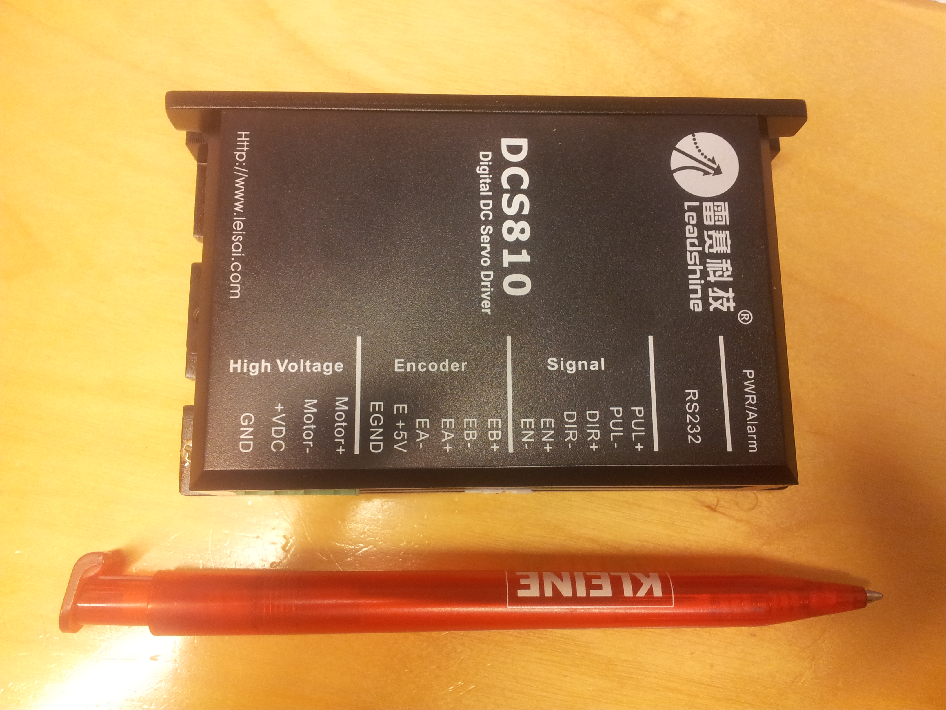
I happened to have some DC-servos around but could not really drive them without a drive (driver, amplifier, controller). I decided to give a Chinese Leadshine DCS810 a try and ordered one from ebay for about 80€.
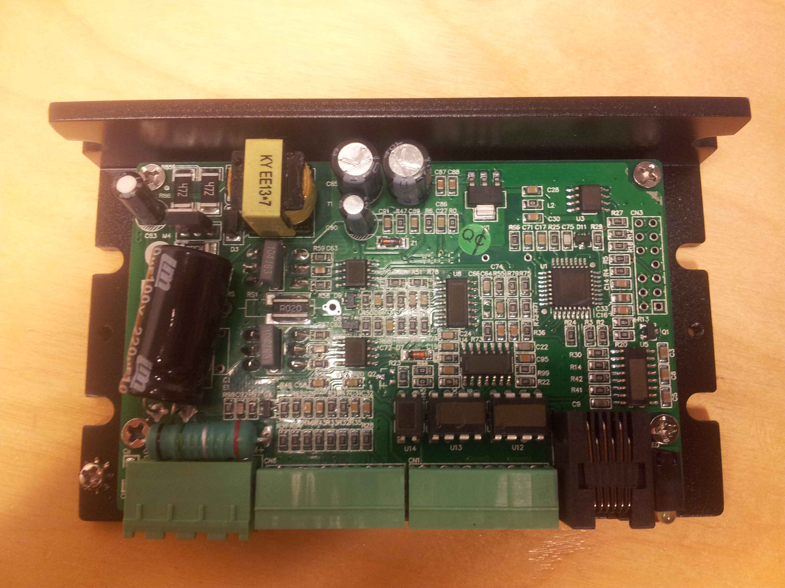
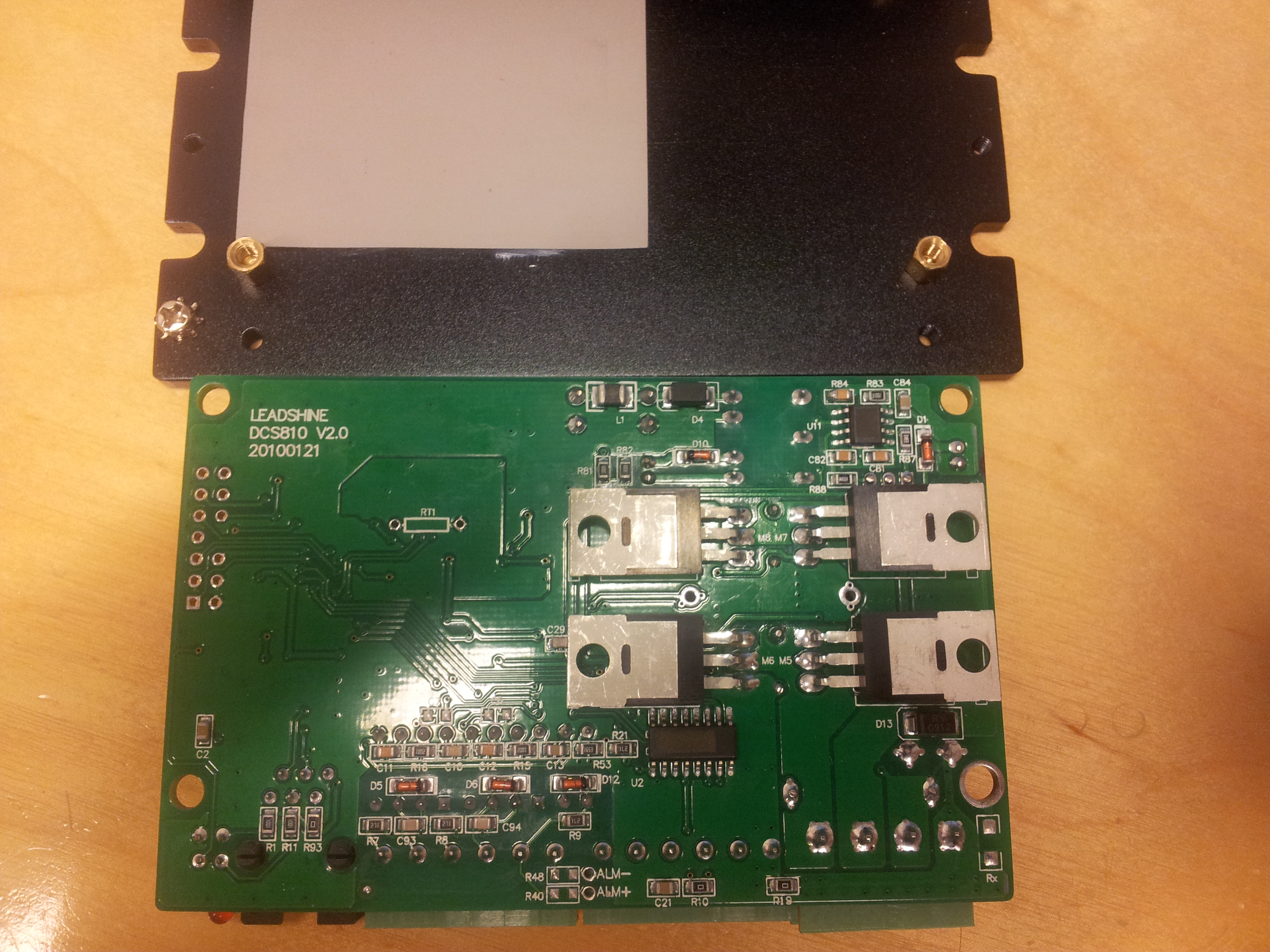
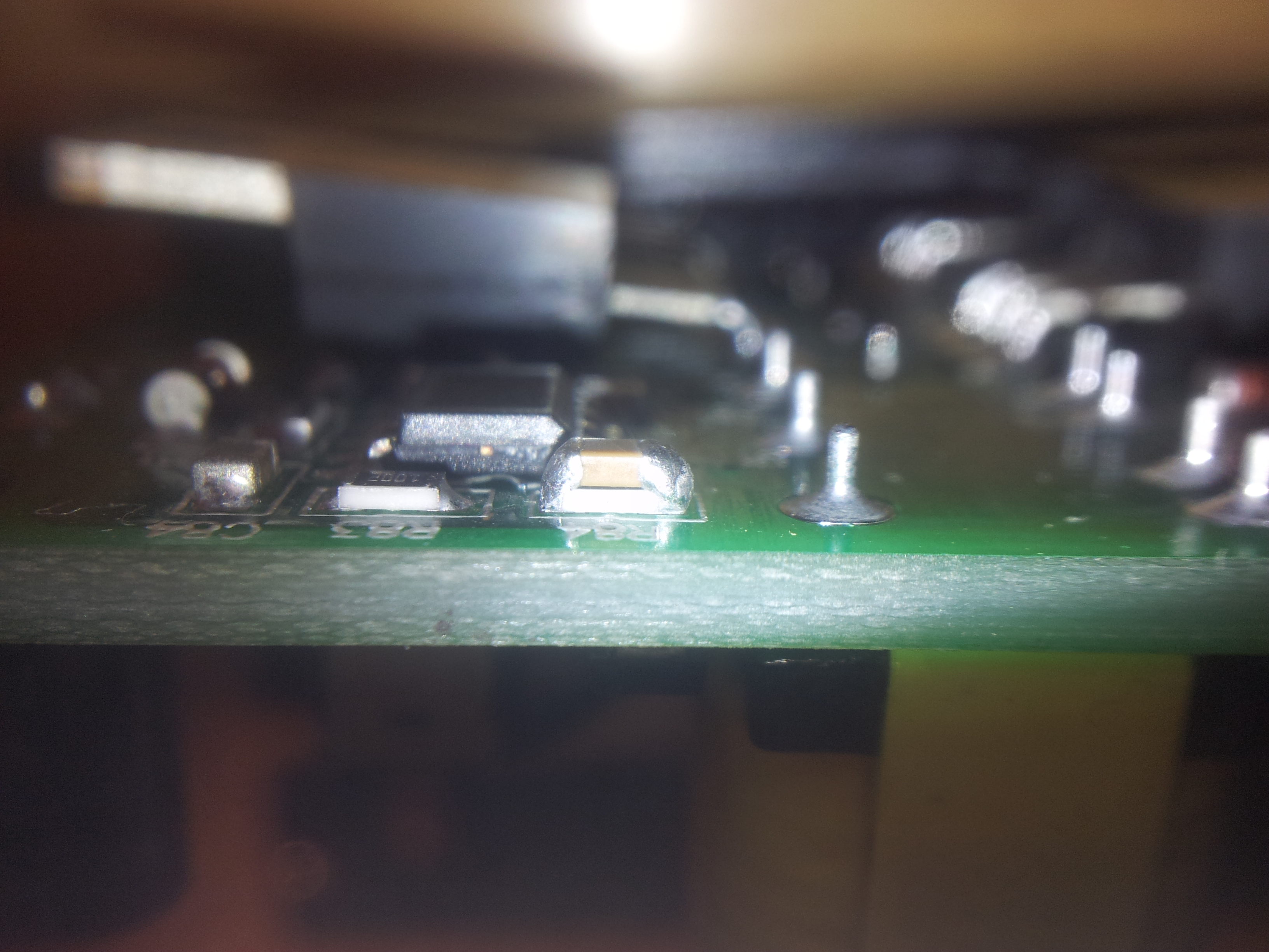
Here are some photos of the device (sorry for bad quatily).
The board seems fairly well constructed with some small quick-fixes for layout.
All markings on IC's have been erased. The FET's used in the H-bridge are IRF540N (Vdss=100, Rds(on)=33mOhm, Id=33A) and are pressed against the aluminium enclosure with silicone insulator for heat dissipation.
As usual with Chinese stuff, the driver came with no instructions what so ever. With google I found a user's manual (leadshine.com/UploadFile/Down/DCS810V1m.pdf). Manual mentiones some resistors that are used for PUL/DIR and CW/CCW Mode Settings. Those resistors on board (R31, R31, R33, R37) are however clearly not the ones mentioned in the manual but serial resistors for the opto-inputs etc. There are 9 jumper resistors on the board (R0, R6, R10, R19, R44, R45, R47, R93, L2) and 2 empty places (R40, R48). As manual states that "Default setting is (b), namely PUL/DIR mode, DIR LOW for positive direction and DIR HIGH for negative direction." I will try controlling the board without modifications to these settings.
More to come when I get to test drive this babe.
added 25.2.2014:
I have a Globe Motors 537A543 servo with hedl-5505 differentian encoder. It can be directly connected to the servo. Another one is a Hirata HRM-020-100-A with DTRE-PWZK encoder. This might be more challenging as it seems to require 12V supply voltage. Figure 8 in the manual represents this situation but does not specify voltage of external DC Power Supply. So I quess it would work fine with 12V PSU.
Stuff to read on the topic: http://www.machsupport.com/forum/index.php?topic=6147 and http://www.cnczone.com/forums/servo-motors-drives/148925-sumtak-encoder.html
Added 26.2.2014:
I got everything wired up using 537A543 motor and two 12V SLA batteries as a power supply. Drive starts up and shows green light while motor stays still and puts some resistance when trying to turn it by hand, so all seems fine so far.
Now I need to find how to tune this system. After googling around I found a pinout for the serial port (http://www.leadshine.com/UploadFile/Down/RJ11%20Connector%20for%20RS232%20Communication.pdf) and possibly the right ?ProTuner software (http://www.leadshine.com/UploadFile/Down/ProTuner_DCS_Setup_2012-11-21.zip)
A "special cable" was of course not provided so I had to improvise. I used and old telephone cord and a female DB9 connector. Then I hooked it up to a usb-RS232 adapter and started the software (DCS810V1.EXE found in the directory). I selected the right serial port and default baudrate and hit "Open". No feedback what so ever. I started to click around. Every time I did anything I was greeted by a message "Please connection and restart!" and had to restart the program. At some point I was able to drive an Err Check without the error message and got one red dot indicating ?EncoderErr at ?ErrCounter 1. I tried another executable "DCS819V2" with same results. How disappointing after such a good start. Maybe my 3m long special cable is too long? I cut it to 1m with no change. Once I ended up in a loop telling me that CRC had failed. Once I was able to open and close Err Check - window twice before a polite request to connection. I tried turning the motor with a little force and was able to produce an error state and see it in Err Check - window. Trying to erase the error gave me a blank look or suggestion to connection and restart. Enough of Chinese software for today.
Added 28.2.2014:
It seems that the USB-RS232-adapter does not produce signals strong enough for the drive. Switching to a port embedded on a pc motherboard made communication rock solid.
I tried ?PositionLoop tuning. Entered right amount of encoder lines for the motor (in my case: 500) and hit "Start?". My motor was spinning! For a couple of seconds it turned one way and then another. Icould see position parameters on the screen. When stopped, motor shaft started vibrating guite heavily. It was really hard to turn the shaft by force. OK, now I need to tune this thing?
I found very little information on tuning in the DCS810V1 manual. After looking aroud I found a DCS810V2 manual with a lot more info. Nice. I learned that tuning must be done with the motor mechanically installed in the system.
I tried controlling it with LinuxCNC and parallel port step/dir signals and it seemed to run nicely ![]() Here's a quick video I shot: http://www.youtube.com/watch?v=EAmzdfbN_fk
Here's a quick video I shot: http://www.youtube.com/watch?v=EAmzdfbN_fk
notes: Minimum pulse length 1us? (manual states: t3: Pulse width not less than 1.0s) -> max frequency = 50kHz?
- started
- 2014-02-28


